A breadboard is a reusable board for building electronics circuits without soldering. For kids learning robotics, it is the safest first tool: push components into the holes, connect jumper wires, test an idea, then rebuild — instead of permanently soldering a PCB.
This beginner breadboard guide explains how the sections and power rails work, how to connect positive and negative supply with jumpers, and how to run a simple LED power-test circuit used in GeekashramJr robotics lessons.
Why Kids Should Learn Breadboards First
- No soldering required for first experiments.
- Mistakes are easy to fix by moving wires and components.
- Students see how LEDs, resistors, buzzers, and buttons connect in real circuits.
- It builds the foundation for Arduino and robotics projects later.
Understanding the Sections of a Breadboard
The breadboard shown below is divided into six parts, and all are electrically separated.
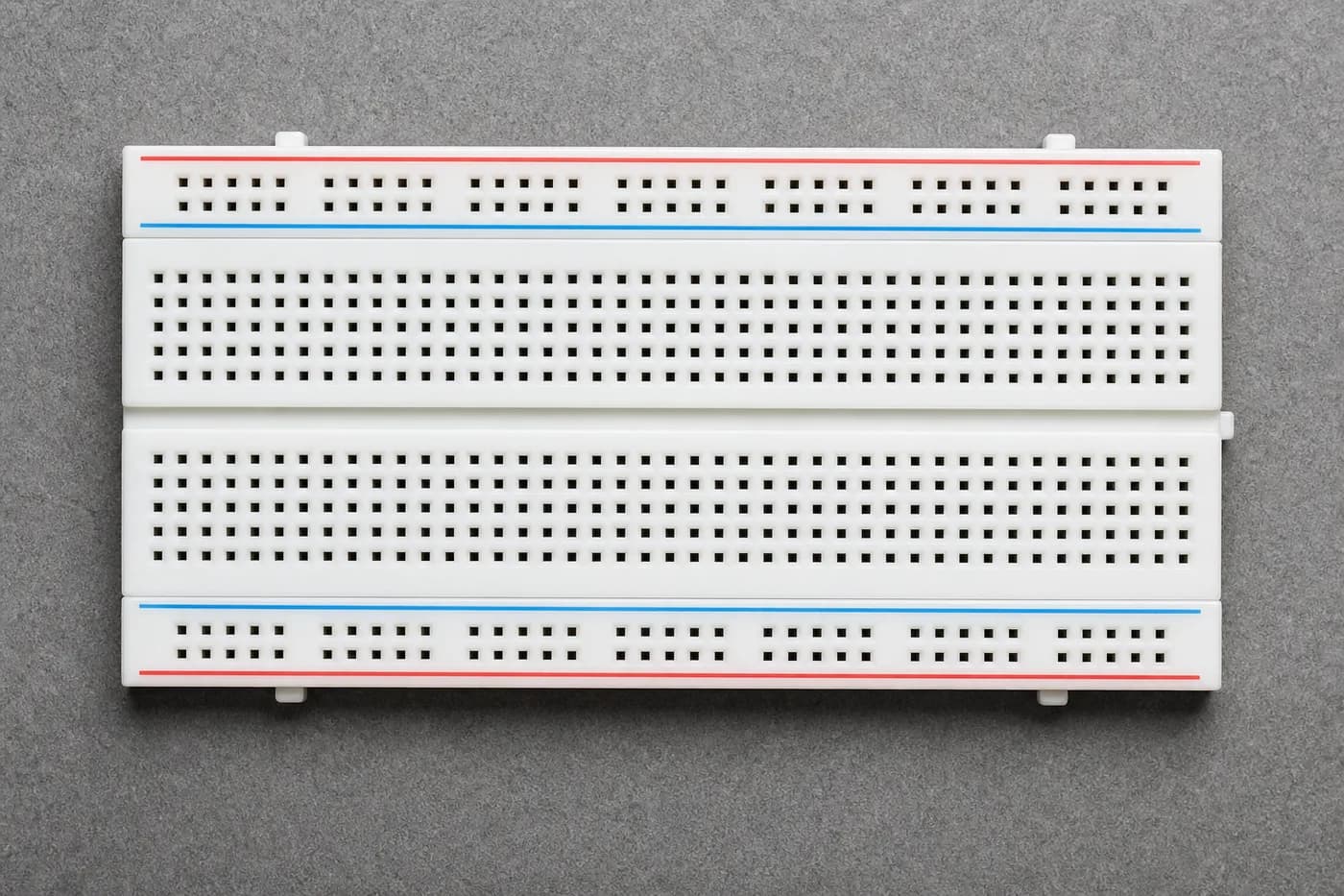
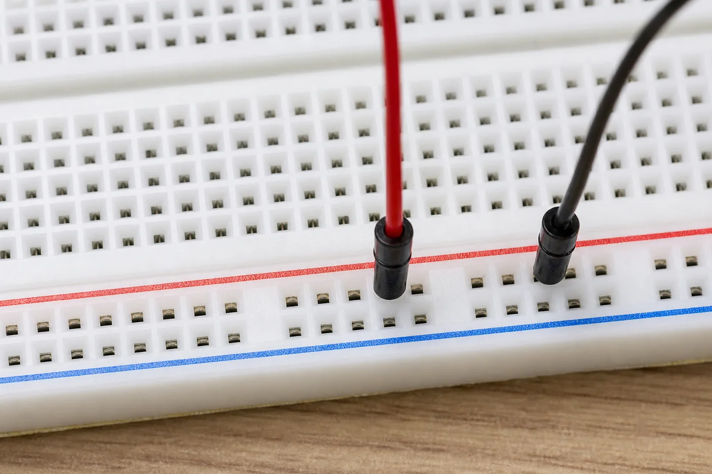
Parts A, B, E, and F: In these parts, each horizontal row is electrically connected internally. These rows are used for the power supply. Note that part A is separated from part B, and part E is separated from part F by the middle split.
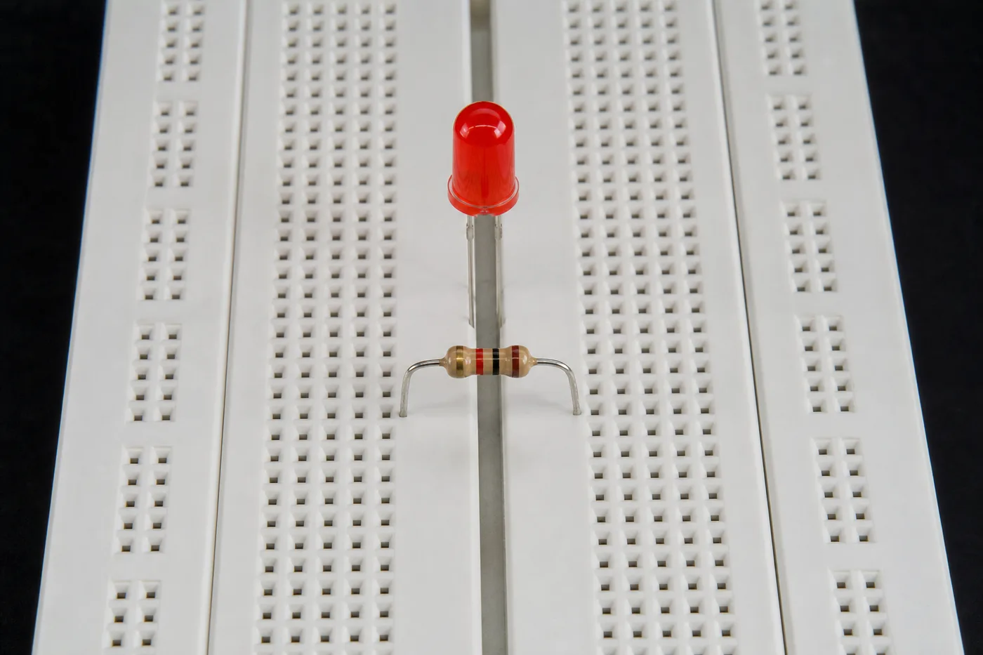
Parts C and D: In these parts, each vertical column is electrically connected internally. These sections are used for making component connections by taking the supply from parts A, B, E, and F with the help of jumper wires.
The internal connections are highlighted below for your reference:
Horizontal power connections
Vertical component connections
Connecting the Power Rails Together
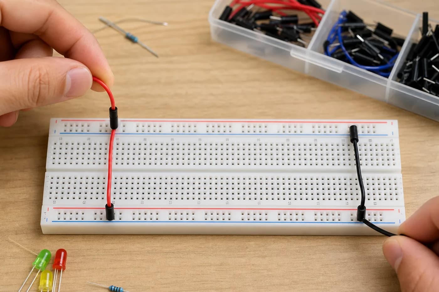
For connecting part A to B, or E to F, we can use jumper wires as per our requirements. The power supply can be given from any side.
In the picture below, the power supply is connected from the upper right corner (see the red and black wires). Jumper wires are then used in the middle to extend the positive and negative supply across the entire length of the board.
Simple LED Experiment
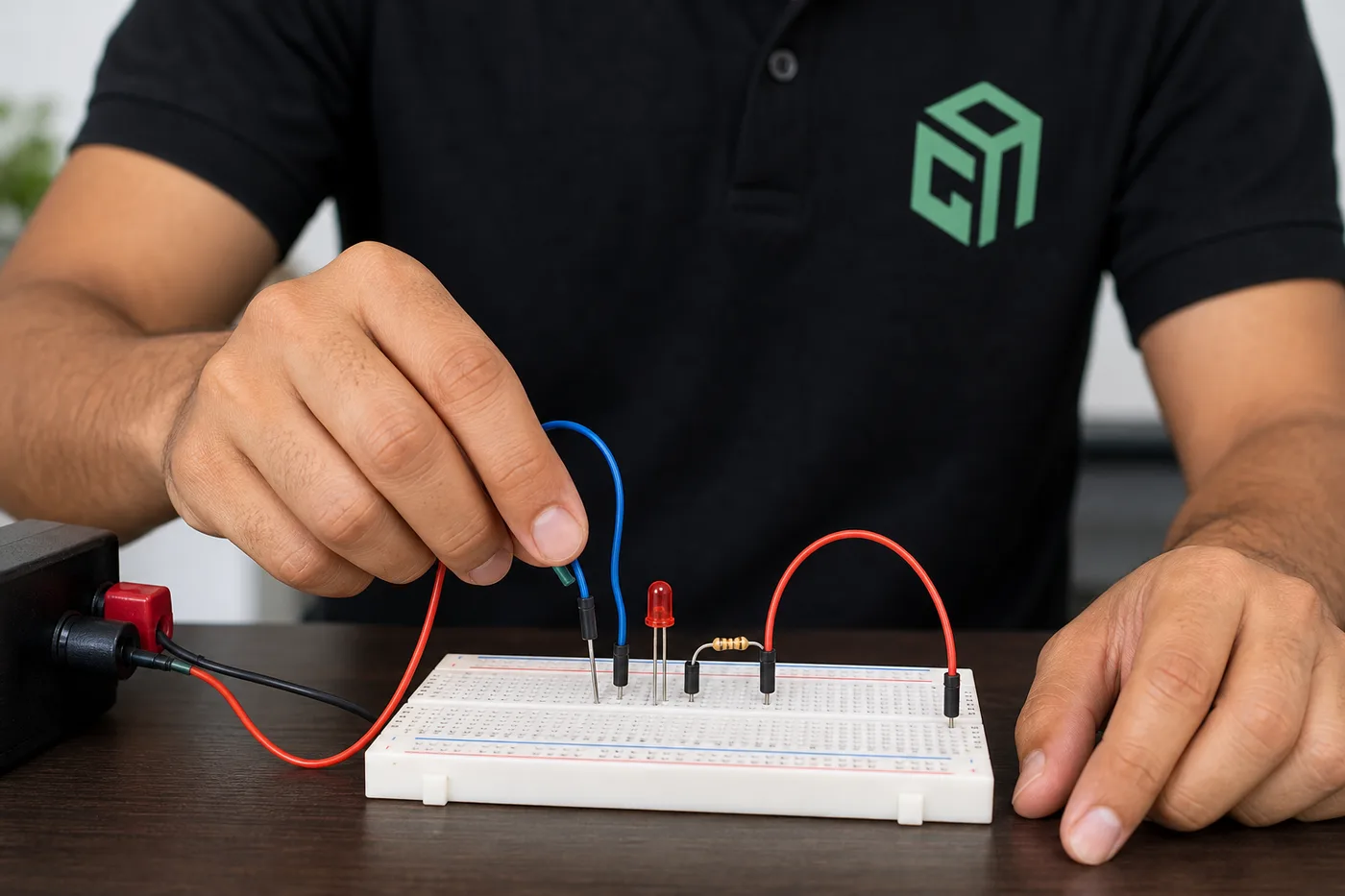
To test the power supply in the breadboard, we can perform a small experiment using an LED.
Components Required:
- Breadboard
- LED (Any color)
- 1k Resistor
- Jumper wires
- 5V to 12V power supply (You can easily use a mobile charger or a battery)
Procedure:
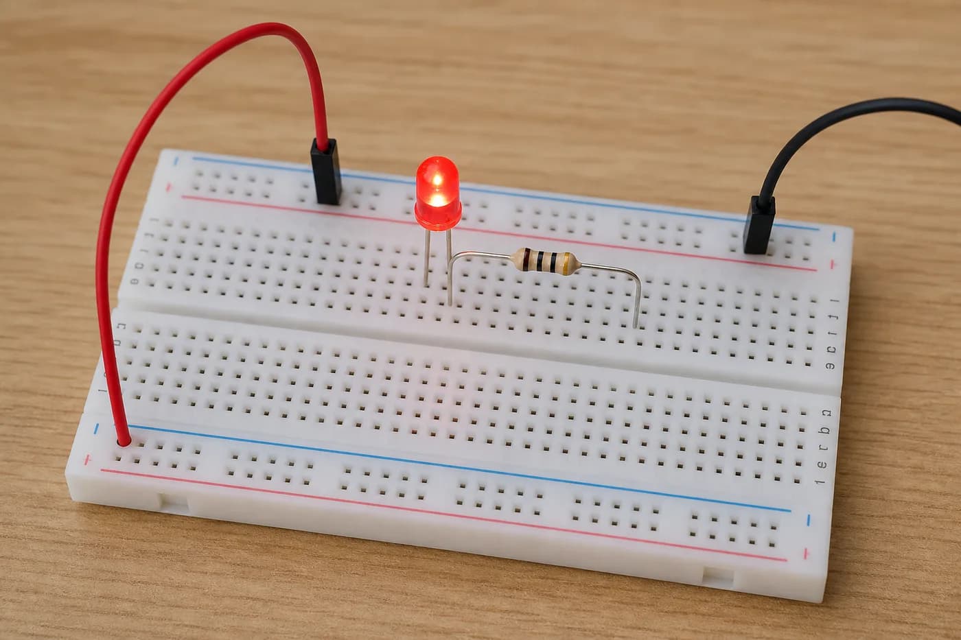
- Connect your main power supply wires into the power rows of part E (Red for positive, Black for negative).
- With the help of a jumper wire, take the positive supply from any hole of the positive row and connect it to a column in part D.
- In the same way, take the negative supply from the negative row using another jumper wire and connect it to a different column in part D.
- Connect the 1k resistor from the positive column to any other empty column. (Resistors have no polarity, so you can connect it either way) .
- Insert the positive leg (the longer leg) of the LED into the same column where the other end of the resistor is connected.
- Insert the negative leg of the LED into the column that you connected to the negative supply rail.
- Finally, switch on the power supply to see the LED light up!
Common Breadboard Mistakes Beginners Make
- Putting both LED legs in the same column, which shorts the circuit.
- Skipping the resistor and risking a burnt LED.
- Mixing up positive and negative rails when extending power with jumpers.
- Assuming every hole is connected — rails and center columns work differently.
Once the LED lights reliably, try the buzzer on a breadboard project, then continue into sensors for kids (LDR, ultrasonic, PIR) and live robotics classes for kids. Parents comparing formats can also read robotics for kids: age, kits & online path.